Chapter 27: NVLink & NVSwitch - The Multi-GPU Interconnect
Every program in the previous chapters ran on a single GPU. Its threads read and wrote the GPU’s own memory, and the only other memory involved was host memory, reached over the link described in Chapter 4. Many applications need more than a single GPU. A model whose parameters do not fit in the memory of a GPU must be divided among several GPUs, and a computation that takes too long on a GPU can be shared among several GPUs to finish sooner. In both cases, the GPUs must exchange data while they compute, and the time spent on that exchange determines how much faster the program runs when GPUs are added.
In this chapter, we study the hardware that carries data between GPUs. We start by counting the bytes that each GPU sends in a step of a data-parallel training program, and the time those bytes take over PCIe. We then describe NVLink, NVIDIA’s interconnect between GPUs, and NVSwitch, the switch that connects many GPUs through NVLink, and we compare the ways in which 4, 8 and 72 GPUs are connected. Finally, we use the CUDA peer-to-peer API, which allows a GPU to copy to and access the memory of another GPU, and the tools that report how the GPUs of a machine are connected.
This chapter covers
- the reasons for using several GPUs, and the data they exchange in each step
- links, differential pairs, and bandwidth in each direction
- the NVLink generations, compared with PCIe and with the memory of the GPU itself
- full meshes, NVSwitch, and the number of links needed for 4, 8 and 72 GPUs
- bisection bandwidth
- unified virtual addressing, peer copies and direct access to a peer’s memory
- the CUDA peer-to-peer API in C++ and in Rust
- a performance model that shows when a faster interconnect helps
- reading the output of
nvidia-smi topo -m
The code of the chapter is in
code/ch18_peer/
for C++ and in
code/oxide/ch18_peer/
for Rust.
27.1 Scaling beyond a single GPU
27.1.1 Capacity and time
There are two reasons to use more than a single GPU, and they lead to different ways of dividing a program.
The first reason is capacity. A language model is defined by its parameters, the numbers that are learned during training. A model with 70 × 109 parameters, stored as 16-bit numbers of 2 bytes each, needs 70 × 109 × 2 = 140 GB for its parameters alone. An H100 has 80 GB of memory. Regardless of how fast the H100 computes, the model does not fit on a single H100. It needs at least 140 / 80 = 1.75, that is, 2 GPUs, and in practice more, because the computation also needs memory for its intermediate values.
The second reason is time. A computation that fits on a single GPU may still take too long there. Training a model repeats the same step many times, each time on a new batch, a group of training examples. If 8 GPUs each process a share of every batch, the training finishes sooner.
27.1.2 Dividing the work among GPUs
A program can be divided among GPUs in three ways, summarized in the following table. The division determines what data the GPUs must send to each other.
| Division | Each GPU holds | What crosses between GPUs |
|---|---|---|
| Data parallelism | a full copy of the model, and its own share of each batch | the results of each step, to be combined into 1 |
| Model parallelism | a part of every layer of the model | partial results inside every layer |
| Pipeline parallelism | whole layers, a few consecutive ones per GPU | each layer’s output, passed to the GPU with the next layer |
Data parallelism is the simplest of the 3, because every GPU runs the unchanged single-GPU program on its share of the data. Model parallelism and pipeline parallelism address the capacity problem, since no GPU holds the whole model. Real systems combine them, for example pipeline parallelism between groups of GPUs and model parallelism within each group. In every case, the GPUs send data to each other at every step.
27.1.3 Communication in data-parallel training
We use data parallelism as our example because its communication is easy to count. A training step computes a gradient for every parameter of the model. The gradient of a parameter is the direction and amount by which the parameter should change to reduce the model’s error on the batch. There is 1 gradient value per parameter, so the gradients occupy as many bytes as the parameters.
In data parallelism, each GPU computes gradients from its own share of the batch, so the gradients differ from GPU to GPU. Before any GPU updates its copy of the model, the gradients of all GPUs must be added, and every GPU must receive the sum. Otherwise, the copies of the model would diverge. The operation that adds a value held by every GPU and gives the sum to every GPU is called an all-reduce. We develop the all-reduce algorithms in Chapter 28; here we only need their cost. With the commonly used ring algorithm, each of \(N\) GPUs sends, and also receives, \(2(N - 1)/N\) times the size of the data.
Let us apply this to a concrete case. A model of 500 × 106 parameters in 16-bit numbers has 500 × 106 × 2 bytes = 1 GB of gradients. On \(N\) = 8 GPUs, each GPU sends 2 × (8 − 1) / 8 × 1 GB = 1.75 GB per step, and receives as much. PCIe 4.0 with 16 lanes, the widest PCIe connection of a GPU (lanes are defined in Section 27.2.1), carries 32 GB/s in each direction (Section 4.1.2), so sending 1.75 GB takes 1.75 / 32 = 0.0547 s, or 54.7 ms. Assume that a single GPU needs 400 ms to compute the step for the whole batch. Each of the 8 GPUs then needs 400 / 8 = 50 ms to compute its share.
The exchange therefore takes longer than the computation it serves. Figure 27.1 shows the resulting step. On 8 GPUs connected by PCIe, a step takes 50 + 54.7 = 104.7 ms, so the 8 GPUs together are only 400 / 104.7 = 3.8 times as fast as a single GPU. With the NVLink of an A100, which carries 300 GB/s in each direction, the exchange takes 1.75 / 300 = 5.8 ms, and the 8 GPUs are 400 / 55.8 = 7.2 times as fast. In Section 27.6, we generalize this example into a model.
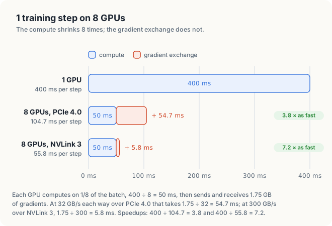
NOTE: Training frameworks start sending the gradients of the last layers while the earlier layers are still being computed, so part of the exchange overlaps with computation, in the same way that the copies of Chapter 6 overlapped with kernels. Overlap can hide at most as much exchange time as there is computation to hide it behind. In this example, at most 50 ms of the 54.7 ms can be hidden, and the step still takes at least 54.7 ms.
Adding GPUs divides the computation of a step, but not the bytes that each GPU must exchange. The interconnect between the GPUs determines how many GPUs still make the program faster.
27.2 NVLink: a faster link between GPUs
27.2.1 Links and differential pairs
Before we describe NVLink, we need 4 terms for the hardware that connects 2 chips. We define them from the outside in: the system of connections, 1 connection, and the wires inside it.
Definition 27.1 Interconnect and link. An interconnect is the hardware that carries data between chips. A link is 1 connection of an interconnect between 2 chips. A link carries data in both directions, and its bandwidth in each direction is the maximum number of bytes that it can move per second in that direction.
Example. PCI Express (PCIe), described in Chapter 4, is the standard interconnect between a CPU and the devices plugged into it. A GPU in a PCIe slot is joined to the CPU by 1 PCIe link.
Both PCIe and NVLink transmit data as electrical signals over differential pairs. A differential pair is 2 wires that carry a signal as the difference between their voltages. Noise from outside affects both wires nearly equally, so the difference is disturbed much less than the voltage on a single wire would be. A pair carries data in 1 direction, so a link that carries data both ways needs pairs in both directions.
Definition 27.2 Lane. A PCIe lane consists of 2 differential pairs, 1 in each direction. A PCIe link is made of 1 or more lanes side by side, and its bandwidth is the number of lanes times the bandwidth of 1 lane.
Example. A lane of PCIe 4.0 carries 2 GB/s in each direction. A GPU in a slot with 16 lanes therefore has 16 × 2 = 32 GB/s in each direction, the figure used in Section 27.1.3.
Definition 27.3 NVLink. NVLink is NVIDIA’s interconnect between GPUs, and in some systems between a GPU and a CPU. It is organized into links, each a bundle of pairs in both directions. A GPU has many NVLink links. It can connect each link to a different GPU, or connect several links to the same GPU.
Example. An H100 has 18 NVLink links. In a server of 8 H100s connected directly, a GPU can give 2 links to each of the other 7 GPUs.
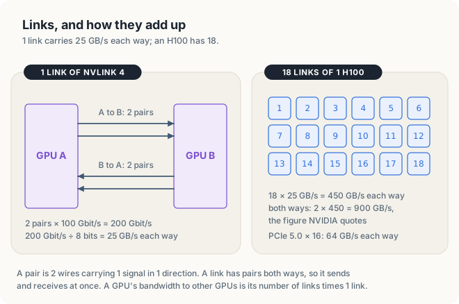
Let us compute the bandwidth of 1 NVLink link from its pairs. A link of NVLink 4, the generation used by the H100, has 2 pairs in each direction, and each pair signals at 100 Gbit/s. A link therefore carries 2 × 100 = 200 Gbit/s in each direction, which is 200 / 8 = 25 GB/s. An H100 has 18 links, for a total of 18 × 25 = 450 GB/s in each direction. The NVLink 3 of the A100 reached the same 25 GB/s per link with 4 pairs in each direction at half the signaling rate. NVLink 4 halved the number of pairs per link and doubled their rate, which leaves room on the chip for more links. Figure 27.2 shows a link and the 18 links of an H100.
27.2.2 Bandwidth in each direction
Recall from Definition 27.1 that the bandwidth of a link is the maximum amount of data it can carry per unit of time. A link with pairs in both directions has 2 bandwidths, 1 for each direction, and both can be used at the same time. NVIDIA quotes NVLink bandwidth as the sum of the two directions: the 900 GB/s quoted for an H100 is 450 GB/s in each direction. PCIe bandwidth is usually quoted per direction, as in Chapter 4: 32 GB/s for PCIe 4.0 with 16 lanes and 64 GB/s for PCIe 5.0.
A comparison between links must use the same convention for both. A GPU that sends its gradients to another GPU sends them in 1 direction, so in this chapter we quote every link per direction. In this unit, NVIDIA’s statement that the NVLink of the H100 has 7 times the bandwidth of PCIe 5.0 is confirmed: 450 / 64 = 7.0. The following table summarizes the quantities for an H100.
| Symbol | Meaning | For an H100 |
|---|---|---|
| \(L\) | links per GPU | 18 |
| \(b\) | bandwidth of 1 link, each way | 25 GB/s |
| \(B = L \cdot b\) | the GPU’s NVLink bandwidth, each way | 18 × 25 = 450 GB/s |
| \(2B\) | both ways, the figure NVIDIA quotes | 900 GB/s |
27.2.3 NVLink generations
Each generation of NVIDIA’s data-center GPUs has introduced a new generation of NVLink. The following table lists NVIDIA’s figures. The column for each direction is half of NVIDIA’s total.
| Link | GPU | Links | Each link, each way | Each way | Both ways (NVIDIA) |
|---|---|---|---|---|---|
| PCIe 4.0 × 16 | A100 PCIe, RTX 4090 | 16 lanes | 2 GB/s per lane | 32 GB/s | 64 GB/s |
| PCIe 5.0 × 16 | H100 PCIe, RTX 5090 | 16 lanes | 4 GB/s per lane | 64 GB/s | 128 GB/s |
| NVLink 2 | V100 | 6 | 25 GB/s | 150 GB/s | 300 GB/s |
| NVLink 3 | A100 | 12 | 25 GB/s | 300 GB/s | 600 GB/s |
| NVLink 4 | H100 | 18 | 25 GB/s | 450 GB/s | 900 GB/s |
| NVLink 5 | B200 | 18 | 50 GB/s | 900 GB/s | 1,800 GB/s |
| NVLink-C2C | GH200, CPU to GPU | 1 chip-to-chip link | 450 GB/s | 900 GB/s |
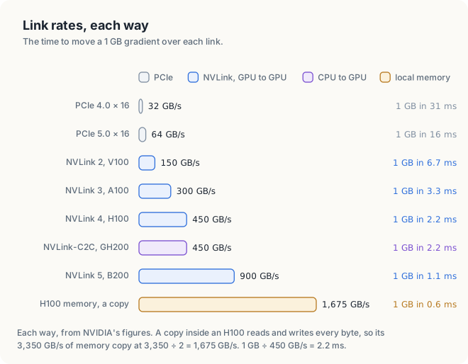
From the V100 to the H100, the rate of a single link stayed at 25 GB/s in each direction, and the bandwidth grew with the number of links: 6, 12 and 18. NVLink 5 instead doubled the rate of each link. The consumer GPUs in the table, the RTX 4090 and RTX 5090, have no NVLink, so 2 of them exchange data over PCIe. Integrated GPUs, such as the one in the DGX Spark, have no NVLink either. Each is the only GPU in its system, and it shares a single memory with the CPU.
Figure 27.3 converts these rates into the time needed to move the 1 GB of gradients from Section 27.1.3.
27.2.4 Peer bandwidth compared with local memory
A GPU’s own memory is still faster than any link. The last bar of Figure 27.3 is a copy within an H100. Its memory delivers 3,350 GB/s, and a copy both reads and writes every byte, so it moves data at 3,350 / 2 = 1,675 GB/s.
Definition 27.4 Peer. A peer of a GPU is another GPU in the same system, and the memory of a peer is called peer memory.
Example. In a server of 8 GPUs, GPU 0 has 7 peers, GPUs 1 to 7.
For a program, the important quantity is how many times slower peer memory is to reach than the GPU’s own memory. The following table uses the SXM versions of the data-center GPUs, which are modules mounted on a server board with NVLink. The same GPUs are also sold as PCIe cards, with different links and memory.
| GPU | Memory | Link to a peer, each way | Memory ÷ link |
|---|---|---|---|
| V100 SXM | 900 GB/s | NVLink 2, 150 GB/s | 6 |
| A100 SXM 80 GB | 2,039 GB/s | NVLink 3, 300 GB/s | 6.8 |
| H100 SXM | 3,350 GB/s | NVLink 4, 450 GB/s | 7.4 |
| B200 | 8,000 GB/s | NVLink 5, 900 GB/s | 8.9 |
| H100 SXM, over PCIe 5.0 | 3,350 GB/s | 64 GB/s | 52 |
Over NVLink, a peer’s memory is 6 to 9 times slower to reach than the GPU’s own memory. Over PCIe it is 52 times slower. This ratio, more than the bandwidth alone, determines which programs can treat several GPUs as 1 large GPU. For example, a kernel that reads 1 byte in 8 from a peer over NVLink spends about as much time on the link as on its own memory.
27.3 NVSwitch and topologies
27.3.1 Full-mesh topology
Once a system has more than 2 GPUs, there is more than 1 way to connect them, and the choice determines how fast each pair of GPUs can exchange data.
Definition 27.5 Topology. The topology of a multi-GPU system is the pattern of links that connects its GPUs: which pairs of chips are joined, and by how many links.
Example. 4 GPUs can be connected in a ring, 0–1–2–3–0, with 4 connections, or with a connection between every pair, with 6 connections. The 2 topologies use the same GPUs but give different bandwidths between GPUs 0 and 2: the ring has no direct connection between them.
The simplest topology gives every pair of GPUs its own link, and is called a full mesh. Let us count the links of a full mesh of 4 GPUs by hand. GPU 0 needs a link to each of GPUs 1, 2 and 3, and so do the other 3 GPUs. The 4 GPUs therefore have 4 × 3 = 12 link ends. Each link has 2 ends, 1 on each of the GPUs that it joins, so the link from GPU 0 to GPU 1 is counted once at GPU 0 and once at GPU 1. The mesh therefore has 12 / 2 = 6 links: 0–1, 0–2, 0–3, 1–2, 1–3 and 2–3. With 8 GPUs, each GPU needs 7 links, and the mesh needs 8 × 7 / 2 = 28. The same count for \(N\) GPUs gives the general rule: a full mesh of \(N\) GPUs needs \(N - 1\) links per GPU and \(N(N - 1)/2\) links in total.
Figure 27.4 shows both cases. The number of links in a mesh grows with the square of the number of GPUs, but the number of links on each GPU is fixed when the chip is designed.
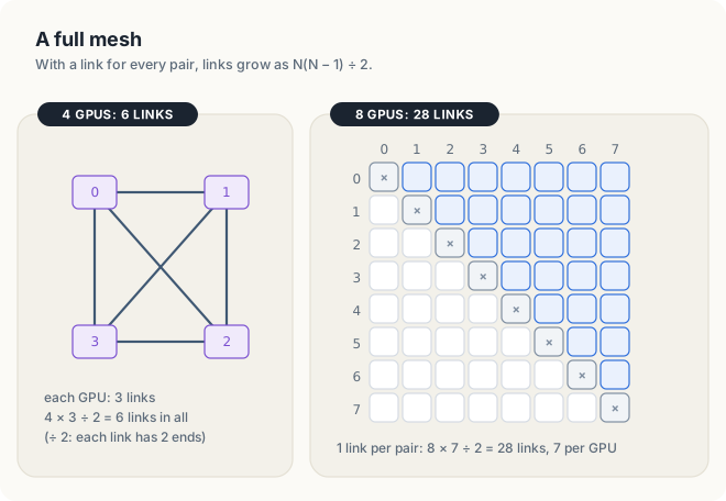
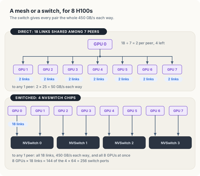
Each GPU must therefore divide its links among its peers. An A100 has 12 links. In a mesh of 4 A100s, each GPU gives 12 / 3 = 4 links to each of its 3 peers, for 4 × 25 = 100 GB/s in each direction per pair. In a mesh of 8 H100s, each GPU could give 2 links to each of its 7 peers (18 / 7, rounded down, with 4 links left over), for 2 × 25 = 50 GB/s in each direction to any single peer. That is a ninth of the GPU’s 450 GB/s. The more GPUs a mesh connects, the less bandwidth is available between any 2 of them.
27.3.2 NVSwitch
A mesh runs out of links because every GPU must have a link of its own to every other GPU. A switch removes this requirement.
Definition 27.6 Switch and NVSwitch. A switch is a chip with many ports, each of which accepts 1 link, and it forwards data arriving at any port to any other port. NVSwitch is NVIDIA’s switch for NVLink. Instead of connecting GPUs to each other, each GPU connects all of its links to switches, and the switches forward its data to whichever GPU it addresses.
Example. 8 GPUs connected through switches need 8 connections, 1 bundle of links from each GPU to the switches, where a full mesh of the same 8 GPUs needs 28 links. A ninth GPU adds 1 more bundle, whereas in the mesh it would add 8 links.
The difference appears when a GPU communicates with a single peer. In a mesh, only the 2 links between the pair carry the data. Through switches, all 18 links of the GPU carry it, at the full 450 GB/s in each direction. A switch that allows every GPU to send at its full rate to any other GPU at the same time is called non-blocking. Figure 27.5 compares the two ways of connecting 8 H100s.
A switch also changes the path that data takes.
Definition 27.7 Hop. A hop is 1 crossing of a link, from 1 chip to the next chip on the path of the data. The latency of a transfer is the time between the start of the transfer and the arrival of its first byte, and every hop adds to it.
Example. In a full mesh, data from GPU 0 to GPU 3 crosses the link 0–3: 1 hop. Through a switch, it crosses the link from GPU 0 to the switch and then the link from the switch to GPU 3: 2 hops.
The switch therefore adds a hop: data travels from the GPU to a switch and then to the peer, and each hop adds latency. For exchanges larger than a few kilobytes, the gain in bandwidth outweighs the added latency.
27.3.3 NVLink systems
NVIDIA’s 8-GPU servers and its rack-scale systems are built from these components.
| System | GPUs | Switches | Each GPU’s links | Any pair, each way |
|---|---|---|---|---|
| DGX A100 | 8 A100 | 6 NVSwitch, 2nd generation | 12, 2 to each switch | 300 GB/s |
| DGX H100 | 8 H100 | 4 NVSwitch, 3rd generation, 64 ports each | 18, spread over the 4 | 450 GB/s |
| GB200 NVL72 | 72 B200 in 1 rack | 18 NVSwitch chips | 18 | 900 GB/s |
In the DGX A100, 12 links per GPU over 6 switches give 12 / 6 = 2 links from every GPU to every switch. In the DGX H100, the 8 GPUs bring 8 × 18 = 144 links to 4 × 64 = 256 switch ports. The third-generation NVSwitch also has ports for switches outside the server, so that up to 256 GPUs can be connected in a single NVLink network. The NVL72 connects 72 GPUs in a rack, each at 1,800 GB/s in both directions together: 72 × 1.8 TB/s = 129.6 TB/s, the 130 TB/s that NVIDIA quotes as the total for the rack.
The third-generation NVSwitch can also perform arithmetic. It can add the data that several GPUs send to it and return the sum, which can halve the number of bytes that some of the collective operations of Chapter 28 must move.
27.3.4 Bisection bandwidth
Topologies differ most when every GPU sends data at the same time, and a single number characterizes this case. Let us derive it on 4 GPUs before we define it. Connect GPUs 0, 1, 2 and 3 in a ring, 0–1–2–3–0, with 1 link of 25 GB/s on each edge, and let GPUs 0 and 1 each send data to GPUs 2 and 3 at the same time. Every byte must cross from the half {0, 1} to the half {2, 3}, and only 2 links join the halves: 1–2 and 3–0. The two halves can therefore exchange at most 2 × 25 = 50 GB/s in each direction, however fast each GPU is.
The answer depends on where we cut. The division into {0, 2} and {1, 3} is crossed by all 4 links of the ring, 100 GB/s. A program cannot choose which halves need to talk to each other, so the number that describes the topology is the worst case, the division crossed by the fewest links: 50 GB/s for this ring. In a full mesh of the same 4 GPUs, with 1 link per pair, every division into two halves of 2 GPUs is crossed by 2 × 2 = 4 links, 100 GB/s.
Definition 27.8 Bisection bandwidth. Divide the GPUs into two halves of equal size, choosing the division that leaves the fewest links crossing between the halves. The bisection bandwidth is the total bandwidth, in each direction, of the links that cross. It is the maximum amount of data that one half can send to the other half per unit of time, for the worst division.
Example. 4 GPUs in a ring with 1 link of 25 GB/s per edge have a bisection bandwidth of 2 × 25 = 50 GB/s; in a full mesh with 1 link per pair, 4 × 25 = 100 GB/s.
Figure 27.6 computes the bisection bandwidth of 8 GPUs, each with 18 links of 25 GB/s, connected in three ways.
Worked example: the bisection bandwidth of 8 GPUs
- Ring. Each GPU connects to its 2 neighbors with 9 links each: 9 × 25 = 225 GB/s per edge. A cut through the ring crosses 2 edges: 2 × 225 = 450 GB/s.
- Mesh. 4 GPUs on each side make 4 × 4 = 16 pairs that cross the cut, each with 2 links: 16 × 2 × 25 = 800 GB/s.
- Switch. Each of the 4 GPUs on one side sends at its full 450 GB/s through the switches: 4 × 450 = 1,800 GB/s.
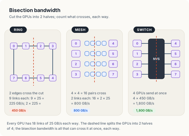
The links are the same in all three cases; only their arrangement differs. Some model-parallel programs make every GPU send to every other GPU at once, in every layer. Such exchanges run at the bisection bandwidth, and a switch gives them 4 times the bandwidth of a ring.
| Symbol | Meaning | For 8 H100s through switches |
|---|---|---|
| \(N\) | GPUs | 8 |
| \(B\) | 1 GPU’s bandwidth, each way | 450 GB/s |
| \(\frac{N}{2} B\) | bisection bandwidth of a non-blocking switch | 4 × 450 = 1,800 GB/s |
A mesh divides each GPU’s links among its peers, while a switch gives every pair all of them. The links that cross the middle of a system determine its performance when every GPU communicates at once.
27.4 Memory access across NVLink
A fast link would be useful even if it only carried copies. Together with CUDA, however, NVLink also allows a GPU to use the memory of another GPU almost as if it were its own. We now describe the 4 mechanisms that make this possible.
27.4.1 Unified virtual addressing
A pointer is a number, an address. Before a GPU can use a pointer into the memory of a peer, the program must be able to tell from that number which memory it refers to. If GPU 0 and GPU 1 each numbered their memory from the same starting address, the same pointer value could mean a byte on GPU 0 or a byte on GPU 1, and a copy function would need to be told which.
Definition 27.9 Unified virtual addressing. On a 64-bit system, CUDA places the host and all GPUs in a single range of virtual addresses. This arrangement is called unified virtual addressing (UVA). No 2 allocations, on any GPU or on the host, receive the same address, so the value of a pointer alone determines which memory it points to.
Example. A program allocates a on GPU 0 and b on GPU 1. Under UVA, the addresses of a and
of b lie in different parts of 1 address range, so the runtime can tell from the value of b
alone that it points into the memory of GPU 1.
The program of Section 27.5 uses cudaPointerGetAttributes to ask the
runtime where a buffer resides. It copies with cudaMemcpyDefault, which tells the runtime to
infer the direction of the copy from the 2 pointers.
UVA is related to the unified memory of Section 4.5, but it provides only part of it: the addresses are shared, while the data stays in the memory where it was allocated.
27.4.2 Peer copies and direct peer access
Data can reach a peer’s memory in two ways, and the program of Section 27.5 measures both.
- A copy.
cudaMemcpyPeerAsyncasks the copy engines of the GPU, the units that move data without using any streaming multiprocessor (SM) (Section 4.2.2), to move a block of bytes from 1 GPU to another. - Direct access. A kernel running on GPU 0 dereferences a pointer into the memory of GPU 1, and each load or store travels over the link. No copy is made, and the kernel reads only the bytes it needs, wherever they are in the peer’s memory.
Definition 27.10 Peer access. Peer access from GPU i to GPU j is the permission for kernels running on GPU i to load from and store to the memory of GPU j through pointers, and for copies from GPU i to GPU j to go directly to that memory. It is granted in 1 direction at a time.
Example. After GPU 0 enables peer access to GPU 1, a kernel on GPU 0 can read b[5] in the
memory of GPU 1. A kernel on GPU 1 still cannot read the memory of GPU 0 until GPU 1 enables peer
access to GPU 0.
Direct access must be enabled, once, with cudaDeviceEnablePeerAccess. Copies work without
it, but the runtime then stages them through host memory. It copies from GPU 0 to the host
and then from the host to GPU 1, crossing PCIe twice where once would suffice. Figure 27.7
shows the 3 paths that a copy can take.
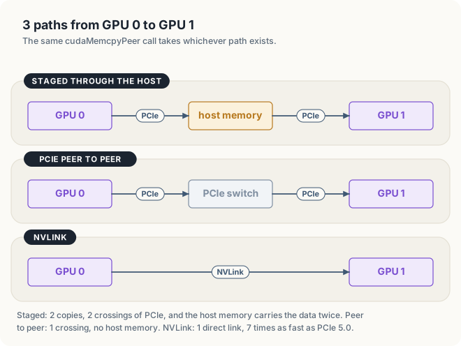
A peer-to-peer (P2P) transfer is any transfer from 1 GPU to another that does not pass
through host memory. In Figure 27.7, the second and third paths are peer-to-peer, and the first is
not. Over PCIe, the platform determines whether P2P is possible. It works most
reliably when the 2 GPUs are behind the same PCIe switch, and many desktop systems do not allow
it at all. Over NVLink it is always possible. cudaDeviceCanAccessPeer reports, for a pair of
GPUs, whether it is.
27.4.3 Atomic operations on peer memory
The atomic operations of Chapter 5 can target a peer’s memory, so threads on 2 GPUs can add to
the same counter. NVLink carries atomic operations as such, and the peer’s memory performs
them. Whether a given pair of GPUs supports this natively is reported by
cudaDeviceGetP2PAttribute with the attribute cudaDevP2PAttrNativeAtomicSupported. Each such
atomic operation crosses the link and waits for its result. Peer atomics are therefore suited
to infrequent events, such as a flag or a work counter, and not to an update per element.
27.4.4 NVLink-C2C and coherence
The Grace Hopper superchip, GH200, connects a Grace CPU and an H100 GPU with NVLink-C2C, a chip-to-chip link of 450 GB/s in each direction. The link is coherent: when the CPU writes a value that the GPU holds in a cache, the hardware updates or invalidates the GPU’s copy, and vice versa, so neither processor reads a stale value. CPU threads and GPU threads can therefore work on the same data at the same time, without copies and without the page migrations of unified memory. Integrated GPUs, such as the one in the DGX Spark, go further. They share a single memory with their CPU, so there is no second memory to copy to.
27.5 Peer-to-peer in CUDA
27.5.1 Structure of the program
The program of this section asks the system three questions and measures the answer to the last:
- How many GPUs are there, and what are they?
- Which GPUs can access the memory of which other GPUs?
- How fast do bytes move from GPU 0 to GPU 1, by a copy and by a kernel?
On a machine with 2 GPUs that can access each other, the copies go from GPU 0 to GPU 1. On a machine with a single GPU, they stay within GPU 0, and the program measures the GPU’s own memory, the baseline against which we compared every link in Section 27.2.4. The following pseudocode summarizes the program.
count ← number of GPUs
print each GPU's name and SMs
for each pair (i, j), i ≠ j:
    print whether GPU i can access GPU j
if count > 1 and GPU 0 can access GPU 1:
    src ← 0, dst ← 1, enable peer access from GPU 0 to GPU 1
else:
    src ← 0, dst ← 0
a ← 128 MiB on GPU src, filled with known values
b ← 128 MiB on GPU dst
for each way in (cudaMemcpyPeerAsync, copy kernel on GPU src):
    b ← 0
    time 50 transfers of a into b, after 0.4 s of warm-up
    check b against the known values
The measurements in this chapter come from 2 integrated GPUs: a Jetson Orin NX (8 SMs, 102 GB/s) and a Jetson AGX Thor (20 SMs, 32 MiB of L2 cache). The buffers are 128 MiB, 4 times the larger of the 2 L2 caches, so the copies measure memory rather than the cache (Chapter 7).
27.5.2 Querying peer access
cudaGetDeviceCount returns the number of GPUs, which are numbered from 0.
cudaDeviceCanAccessPeer sets its first argument to 1 if the GPU given by its second argument
can access the memory of the GPU given by its third argument. Note that the query has a
direction: whether GPU 0 can access GPU 1 and whether GPU 1 can access GPU 0 are queried, and
enabled, separately. Listing 27.1 prints the resulting matrix.
Listing 27.1 The number of GPUs and the peer matrix. Rust C++
fn device_count() -> Result<usize, DriverError> {
    let mut count = 0;
    // SAFETY: `count` is a valid place for the driver to write 1 integer, and the driver
    // was initialized by `CudaContext::new` before this call.
    unsafe { cuda_core::sys::cuDeviceGetCount(&mut count).result()? };
    Ok(count as usize)
}

/// The peer matrix: can the GPU of each row read and write the memory of each column?
fn print_peer_matrix(gpus: &[Arc<CudaContext>]) -> Result<(), DriverError> {
    print!("peer access (row can reach column):\n      ");
    for j in 0..gpus.len() {
        print!("  GPU{j}");
    }
    println!();

    for (i, from) in gpus.iter().enumerate() {
        print!("  GPU{i}");

        for (j, to) in gpus.iter().enumerate() {
            let cell = if i == j {
                "X"
            } else if peer::can_access_peer(from, to)? {
                "yes"
            } else {
                "no"
            };
            print!("  {cell:>4}");
        }
        println!();
    }
    Ok(())
}
// The peer matrix: can the GPU of each row read and write the memory of each column?
void printPeerMatrix(int count)
{
std::printf("peer access (row can reach column):\n ");
for (int j = 0; j < count; ++j) {
std::printf(" GPU%d", j);
}
std::printf("\n");
for (int i = 0; i < count; ++i) {
std::printf(" GPU%d", i);
for (int j = 0; j < count; ++j) {
int ok = 0;
if (i != j) check(cudaDeviceCanAccessPeer(&ok, i, j));
const char* cell = i == j ? "X" : ok ? "yes" : "no";
std::printf(" %4s", cell);
}
std::printf("\n");
}
}
cuda-core, the host library of cuda-oxide, provides the same query as
peer::can_access_peer(from, to) between 2 CudaContexts. At revision b7fe543 it has no
function that returns the number of GPUs, so the Rust program calls the driver function
cuDeviceGetCount through cuda_core::sys, the raw driver bindings, in a single unsafe
line. The driver must already be initialized when the call is made, which
CudaContext::new(0) ensures.
27.5.3 Enabling peer access and allocating the buffers
cudaDeviceEnablePeerAccess(peer, 0) allows the current GPU, selected with cudaSetDevice, to
access the memory of the GPU peer. The second argument is reserved for flags and must be 0.
The call maps the peer’s memory into the page tables of the current GPU. This mapping takes
time, so the call is made once and not inside a loop.
Listing 27.2 Choosing the 2 GPUs and enabling access.
fn main() -> Result<(), Error> {
// ...
// Copy from GPU 0 to GPU 1 if GPU 0 can reach it, otherwise within GPU 0.
let reachable = count > 1 && peer::can_access_peer(&gpus[0], &gpus[1])?;
let (src, dst) = if reachable { (0, 1) } else { (0, 0) };
if reachable {
peer::enable_peer_access(&gpus[src], &gpus[dst])?;
} else {
println!("no peer to reach: copying within GPU0");
}
// ...
}int main()
{
// ...
// Copy from GPU 0 to GPU 1 if GPU 0 can reach it, otherwise within GPU 0.
int src = 0;
int dst = 0;
int ok = 0;
if (count > 1) check(cudaDeviceCanAccessPeer(&ok, 0, 1));
if (ok) {
dst = 1;
check(cudaSetDevice(src));
check(cudaDeviceEnablePeerAccess(dst, 0));
} else {
std::printf("no peer to reach: copying within GPU0\n");
}
// ...
}
peer::enable_peer_access(from, to) corresponds to cudaDeviceEnablePeerAccess; it also
returns Ok when access is already enabled.
Each buffer is allocated on its own GPU. Since cudaMalloc allocates on the current GPU, the
program selects GPU src before allocating a and GPU dst before allocating b.
cudaPointerGetAttributes then determines, from the pointer b alone, which GPU holds the
buffer.
Listing 27.3 A buffer on each GPU, and, in C++, the location of b reported through UVA.
fn main() -> Result<(), Error> {
// ...
let host: Vec<f32> = (0..N).map(|i| (i % 1000) as f32).collect();
let stream = gpus[src].new_stream()?;
let dst_stream = gpus[dst].new_stream()?;
let a = DeviceBuffer::from_host(&stream, &host)?;
let mut b = DeviceBuffer::<f32>::zeroed(&dst_stream, N)?;
// ...
}int main()
{
// ...
float* a;
float* b;
check(cudaSetDevice(src));
check(cudaMalloc(&a, BYTES));
check(cudaSetDevice(dst));
check(cudaMalloc(&b, BYTES));
check(cudaMemcpy(a, host.data(), BYTES, cudaMemcpyDefault));
// Unified addressing: the pointer alone tells the runtime which GPU holds it.
cudaPointerAttributes where;
check(cudaPointerGetAttributes(&where, b));
std::printf("buffer b lives on GPU%d\n", where.device);
// ...
}
In Rust, each GPU has its own CudaContext and its own stream, and a DeviceBuffer is
allocated on the GPU whose stream creates it.
27.5.4 Peer copies and copy kernels
The first method is a copy. cudaMemcpyPeerAsync(dst pointer, dst GPU, src pointer, src GPU, bytes, stream) names both GPUs, and when peer access is enabled the copy goes directly across
the link. With a single GPU, the source and destination are both GPU 0, and the call performs
an ordinary copy within its memory. The second method is a kernel running on GPU src in which
each thread copies 1 float from a to b. On 2 GPUs, the stores of this kernel are written to
the peer’s memory.
Listing 27.4 The copy kernel.
#[cuda_module]
mod kernels {
use super::*;
#[kernel]
#[launch_contract(domain = 1, block = (256, 1, 1))]
pub fn copy(src: &[f32], mut dst: DisjointSlice<f32>) {
let idx = thread::index_1d();
let i = idx.get();
if let Some(out) = dst.get_mut(idx) {
*out = src[i];
}
}
}__global__ void copyKernel(const float* src, float* dst, size_t n)
{
size_t i = size_t(blockIdx.x) * blockDim.x + threadIdx.x;
if (i < n) dst[i] = src[i];
}
Listing 27.5 A copy and a kernel, each timed and checked.
fn main() -> Result<(), Error> {
// ...
let ms_peer = average_ms(&stream, || Ok(b.copy_from_device_async(&a, &stream)?))?;
let ok_peer = b.to_host_vec(&dst_stream)? == host;
report("copy_from_device_async", ms_peer, ok_peer);
b = DeviceBuffer::<f32>::zeroed(&dst_stream, N)?;
gpus[src].bind_to_thread()?;
let ms_kernel = average_ms(&stream, || Ok(module.copy(&stream, &launch, &a, &mut b)?))?;
let ok_kernel = b.to_host_vec(&dst_stream)? == host;
report("copy kernel on GPU0", ms_kernel, ok_kernel);
// ...
}int main()
{
// ...
auto peerCopy = [&] {
check(cudaMemcpyPeerAsync(b, dst, a, src, BYTES, stream));
};
unsigned blocks = unsigned((N + 255) / 256);
auto kernelCopy = [&] {
copyKernel<<<blocks, 256, 0, stream>>>(a, b, N);
};
clear(b, dst);
float msPeer = averageMs(peerCopy, stream);
bool okPeer = matches(b, host);
report("cudaMemcpyPeerAsync", msPeer, okPeer);
clear(b, dst);
float msKernel = averageMs(kernelCopy, stream);
check(cudaGetLastError());
bool okKernel = matches(b, host);
report("copy kernel on GPU0", msKernel, okKernel);
// ...
}
The function averageMs first runs its argument for 0.4 s so that the GPU’s clock can rise,
as measured in Chapter 6, and then times 50 runs with events. The function matches copies b
back to the host and compares all 33,554,432 floats with the values written into a. The
function clear sets b to 0 before each method, so that a method that copies nothing cannot
pass by finding the result of the previous method.
In Rust, DeviceBuffer::copy_from_device_async performs the copy. It calls the driver’s
device-to-device copy, which, with UVA, also works between GPUs. The kernel uses the 1-D launch
contract of Chapter 13: src is a plain slice, and DisjointSlice allows each thread to write
its own element of dst without unsafe code.
27.5.5 Results
$ nvcc -arch=native peer.cu -o peer && ./peer
GPUs: 1
GPU0 Orin, 8 SMs, unified addressing yes
peer access (row can reach column):
GPU0
GPU0 X
no peer to reach: copying within GPU0
buffer b lives on GPU0
128 MiB from GPU0 to GPU0, average of 50 copies
cudaMemcpyPeerAsync 3.462 ms 38.8 GB/s PASSED
copy kernel on GPU0 3.677 ms 36.5 GB/s PASSED
The first lines of the output are as expected. There is 1 GPU, so the matrix contains only its
diagonal, X, and the program copies within GPU 0. UVA is enabled, and
cudaPointerGetAttributes reports that b resides on GPU 0. On the second GPU, the program
prints the same first lines:
$ ./peer
GPUs: 1
GPU0 NVIDIA Thor, 20 SMs, unified addressing yes
peer access (row can reach column):
GPU0
GPU0 X
no peer to reach: copying within GPU0
buffer b lives on GPU0
Both copies pass on this GPU as well, in C++ and in Rust.
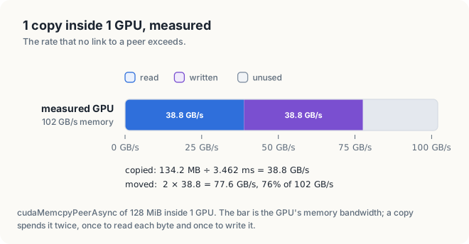
To interpret the rates, we use the reasoning of Section 27.2.4. A copy of 128 MiB, which is 134.2 MB, in 3.462 ms corresponds to 134.2 / 3.462 = 38.8 GB/s copied. Every copied byte is read once and written once, so the memory moved 2 × 38.8 = 77.6 GB/s, which is 76% of the GPU’s 102 GB/s. A copy cannot use all of the memory bandwidth, because the memory loses time each time it switches between reading and writing. The copy kernel ran within 6% of the copy call; in both cases the memory, not the SMs, limited the rate. Across 6 runs, the copy measured between 38.8 and 42.3 GB/s, a spread of 9%.
The Rust program prints the same lines except the UVA details, because cuda-core does not provide the pointer query at this revision.
$ cargo oxide run
GPUs: 1
GPU0 Orin, 8 SMs
peer access (row can reach column):
GPU0
GPU0 X
no peer to reach: copying within GPU0
128 MiB from GPU0 to GPU0, average of 50 copies
copy_from_device_async 3.528 ms 38.0 GB/s PASSED
copy kernel on GPU0 3.769 ms 35.6 GB/s PASSED
copy_from_device_async calls the same driver copy as the C++ program, and it ran within 2% of
it, which is within the spread between runs.
27.5.6 Output on a multi-GPU system
On a server with 8 GPUs connected through NVSwitch, the matrix contains yes in every cell off
the diagonal, because every GPU can reach every other GPU through the switches. On a desktop
with 2 consumer GPUs on PCIe, it may contain no. In that case, the copy still works, but it is
staged through host memory. When GPU 0 can access GPU 1, the program prints buffer b lives on GPU1, and the 2 rates are those of the link rather than of memory; between 2 H100s they can
approach 450 GB/s in each direction. The rate of a copy within a single GPU is an upper bound
that no link to a peer exceeds.
TIP: Run peer on a multi-GPU machine, such as a cloud instance with 2 or 8 GPUs, and
compare its rates with the table of Section 27.2.3. A rate far below the table usually means
that the copies are being staged through the host; check the matrix for no.
27.6 When a faster interconnect helps
27.6.1 A model of a training step
In Section 27.1.3, we computed the time of a step by hand. Writing the same arithmetic with symbols tells us when a faster link improves performance. Let a step take \(T_1\) on a single GPU. On \(N\) GPUs, each GPU computes for \(T_1 / N\) and then exchanges data for \(T_x\), a time that does not decrease with \(N\):
\[ T_N = \frac{T_1}{N} + T_x, \qquad S = \frac{T_1}{T_N} \]
| Symbol | Meaning | 8 A100s on PCIe 4.0 | 8 A100s on NVLink 3 |
|---|---|---|---|
| \(T_1\) | 1 step on 1 GPU | 400 ms | 400 ms |
| \(N\) | GPUs | 8 | 8 |
| \(T_x\) | exchange per step: bytes ÷ link, each way | 1.75 GB ÷ 32 GB/s = 54.7 ms | 1.75 GB ÷ 300 GB/s = 5.8 ms |
| \(T_N\) | 1 step on \(N\) GPUs | 50 + 54.7 = 104.7 ms | 50 + 5.8 = 55.8 ms |
| \(S\) | speedup | 400 ÷ 104.7 = 3.8 | 400 ÷ 55.8 = 7.2 |
The model is Amdahl’s law from Section 1.3, with \(T_x\) as the part that does not divide among processors, and its conclusion is the same: when \(T_x\) is comparable to \(T_1/N\), adding GPUs brings little benefit. The link determines \(T_x\), and therefore the number of GPUs that still improve performance.
For example, suppose we require the exchange to take at most a quarter of each GPU’s computation time, \(T_x \le T_1 / (4N)\), which here is 400 / 32 = 12.5 ms. Over PCIe 4.0, \(T_x\) = 54.7 ms, 4.4 times too long. Over NVLink 3, \(T_x\) = 5.8 ms, within the limit. The model also shows how the balance changes with the workload. Doubling the size of the model doubles both \(T_1\) and the number of bytes exchanged, so their ratio does not change. Halving the batch halves \(T_1\) but not the bytes, so the exchange becomes relatively more important.
27.6.2 Workloads and interconnect requirements
The model classifies programs by the ratio of their exchange time to their computation time.
| Workload | Exchange per step | Link |
|---|---|---|
| data-parallel training of a large model | all gradients, every step | NVLink pays off |
| model parallelism inside every layer | partial results, every layer | NVLink needed |
| graph analytics, databases spread over GPUs | small, scattered reads of peers’ memory | NVLink pays off |
| many independent jobs, 1 per GPU | none | PCIe is enough |
| loading a dataset once, then computing for hours | once | PCIe is enough |
| inference of a model that fits on 1 GPU | none between GPUs | PCIe is enough |
The entries of the table follow from the arithmetic of the model rather than from fixed rules. To decide for a given program, measure the 2 terms: \(T_1\) with the events of Chapter 6, and \(T_x\) with the program of Section 27.5 or with nccl-tests, which we introduce in Chapter 28.
27.7 Topology discovery
27.7.1 nvidia-smi topo -m
A program cannot choose good pairs of GPUs without knowing how they are connected. The command
nvidia-smi topo -m prints the topology as a matrix with 1 row and one column per GPU, and each
cell contains a code for the path between the 2 GPUs. On the second GPU of Section 27.5.5, it
prints the following:
$ nvidia-smi topo -m
GPU0 CPU Affinity NUMA Affinity GPU NUMA ID
GPU0 X 0-13 0 N/A
Legend:
X = Self
SYS = Connection traversing PCIe as well as the SMP interconnect between NUMA nodes (e.g., QPI/UPI)
NODE = Connection traversing PCIe as well as the interconnect between PCIe Host Bridges within a NUMA node
PHB = Connection traversing PCIe as well as a PCIe Host Bridge (typically the CPU)
PXB = Connection traversing multiple PCIe bridges (without traversing the PCIe Host Bridge)
PIX = Connection traversing at most a single PCIe bridge
NV# = Connection traversing a bonded set of # NVLinks
The matrix has a single cell, X, which is the GPU itself. The other columns identify the CPU
cores closest to the GPU, here cores 0 to 13. A NUMA node is a group of CPU cores together
with the memory attached to them; the GPU belongs to node 0, the only node of this system. On
some integrated GPUs, nvidia-smi does not implement the matrix and prints Failed to run topology matrix.
27.7.2 Connection codes
The legend lists the paths from the fastest, at the bottom, to the slowest, at the top. A PCIe bridge is a PCIe switch. A host bridge is the point where PCIe enters the CPU. An SMP interconnect connects the CPU sockets of a server with more than one CPU.
| Code | Path between the 2 GPUs | Peer to peer |
|---|---|---|
NV# | # NVLinks, bonded into 1 connection | yes, over NVLink |
PIX | at most 1 PCIe switch | usually possible |
PXB | several PCIe switches, not through the CPU | often possible |
PHB | through the CPU’s host bridge | depends on the platform |
NODE | between host bridges of 1 CPU | rarely |
SYS | across CPU sockets | no; staged through the host |
Figure 27.9 shows a matrix of this form for an example server with 4 GPUs on 2 CPU sockets, in which GPUs 0 and 1, and GPUs 2 and 3, are connected by 4 NVLinks. The figure illustrates the format; it is not output from a real machine.
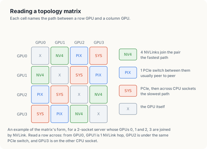
On such a server, a program that uses 2 GPUs should choose GPUs 0 and 1, or GPUs 2 and 3. Choosing GPUs 0 and 3 would send every byte across the CPU sockets.
27.7.3 NVLink status and NVML
nvidia-smi nvlink -s lists the NVLinks of each GPU, with the rate of each link and whether it
is active. On a GPU that is the only GPU in its system, it prints Device does not have or support Nvlink. A program that must adapt to the machine can read the same information from
NVML, the library on which nvidia-smi is built. nvmlDeviceGetTopologyCommonAncestor
returns the nearest common point on the paths of 2 GPUs, which corresponds to the codes of the
table above, and nvmlDeviceGetNvLinkState reports the state of each link.
27.8 The complete programs
Listing 27.6 The complete programs. code/oxide/ch18_peer/src/main.rs code/ch18_peer/peer.cu
//! Chapter 18 in Rust: which GPUs can reach each other's memory, and how fast bytes move.
//!
//! cargo oxide run
//!
//! With 2 or more GPUs that can reach each other, the copies go from GPU 0 to GPU 1.
//! With 1 GPU, they stay inside GPU 0 and measure its own memory instead.
use std::sync::Arc;
use std::time::{Duration, Instant};
use cuda_core::sys::CUevent_flags_enum_CU_EVENT_DEFAULT as TIMING;
use cuda_core::{CudaContext, CudaStream, DeviceBuffer, DriverError, IntoResult};
use cuda_core::{LaunchConfig1D, peer};
use cuda_device::{DisjointSlice, cuda_module, kernel, launch_contract, thread};
const N: usize = 32 << 20; // 33,554,432 floats, 128 MiB
const BYTES: usize = N * 4;
const REPS: u32 = 50;
type Error = Box<dyn std::error::Error>;
#[cuda_module]
mod kernels {
use super::*;
#[kernel]
#[launch_contract(domain = 1, block = (256, 1, 1))]
pub fn copy(src: &[f32], mut dst: DisjointSlice<f32>) {
let idx = thread::index_1d();
let i = idx.get();
if let Some(out) = dst.get_mut(idx) {
*out = src[i];
}
}
}
fn device_count() -> Result<usize, DriverError> {
let mut count = 0;
// SAFETY: `count` is a valid place for the driver to write 1 integer, and the driver
// was initialized by `CudaContext::new` before this call.
unsafe { cuda_core::sys::cuDeviceGetCount(&mut count).result()? };
Ok(count as usize)
}
/// The peer matrix: can the GPU of each row read and write the memory of each column?
fn print_peer_matrix(gpus: &[Arc<CudaContext>]) -> Result<(), DriverError> {
print!("peer access (row can reach column):\n ");
for j in 0..gpus.len() {
print!(" GPU{j}");
}
println!();
for (i, from) in gpus.iter().enumerate() {
print!(" GPU{i}");
for (j, to) in gpus.iter().enumerate() {
let cell = if i == j {
"X"
} else if peer::can_access_peer(from, to)? {
"yes"
} else {
"no"
};
print!(" {cell:>4}");
}
println!();
}
Ok(())
}
/// Average time of 1 run of `run`, in milliseconds, after 0.4 s of warm-up runs.
fn average_ms(
stream: &CudaStream,
mut run: impl FnMut() -> Result<(), Error>,
) -> Result<f32, Error> {
let begin = Instant::now();
while begin.elapsed() < Duration::from_millis(400) {
run()?;
stream.synchronize()?;
}
let start = stream.record_event(Some(TIMING))?;
for _ in 0..REPS {
run()?;
}
let stop = stream.record_event(Some(TIMING))?;
stop.synchronize()?;
Ok(start.elapsed_ms(&stop)? / REPS as f32)
}
fn report(how: &str, ms: f32, ok: bool) {
let gb_per_s = BYTES as f64 / 1e9 / (ms as f64 / 1e3);
let verdict = if ok { "PASSED" } else { "FAILED" };
println!(" {how:<26} {ms:7.3} ms {gb_per_s:7.1} GB/s {verdict}");
}
fn main() -> Result<(), Error> {
let first = CudaContext::new(0)?;
let count = device_count()?;
println!("GPUs: {count}");
let mut gpus = vec![first];
for d in 1..count {
gpus.push(CudaContext::new(d)?);
}
for (d, gpu) in gpus.iter().enumerate() {
let name = gpu.device_name()?;
let sms = gpu.multiprocessor_count()?;
println!(" GPU{d} {name}, {sms} SMs");
}
print_peer_matrix(&gpus)?;
// Copy from GPU 0 to GPU 1 if GPU 0 can reach it, otherwise within GPU 0.
let reachable = count > 1 && peer::can_access_peer(&gpus[0], &gpus[1])?;
let (src, dst) = if reachable { (0, 1) } else { (0, 0) };
if reachable {
peer::enable_peer_access(&gpus[src], &gpus[dst])?;
} else {
println!("no peer to reach: copying within GPU0");
}
let host: Vec<f32> = (0..N).map(|i| (i % 1000) as f32).collect();
let stream = gpus[src].new_stream()?;
let dst_stream = gpus[dst].new_stream()?;
let a = DeviceBuffer::from_host(&stream, &host)?;
let mut b = DeviceBuffer::<f32>::zeroed(&dst_stream, N)?;
gpus[src].bind_to_thread()?;
// SAFETY: the loaded code was compiled from the `kernels` module above.
let module = unsafe { kernels::load(&gpus[src])? };
let launch = module.prepare_copy(LaunchConfig1D::new((N / 256) as u32, 256, 0))?;
println!("{} MiB from GPU{src} to GPU{dst}, average of {REPS} copies", BYTES >> 20);
let ms_peer = average_ms(&stream, || Ok(b.copy_from_device_async(&a, &stream)?))?;
let ok_peer = b.to_host_vec(&dst_stream)? == host;
report("copy_from_device_async", ms_peer, ok_peer);
b = DeviceBuffer::<f32>::zeroed(&dst_stream, N)?;
gpus[src].bind_to_thread()?;
let ms_kernel = average_ms(&stream, || Ok(module.copy(&stream, &launch, &a, &mut b)?))?;
let ok_kernel = b.to_host_vec(&dst_stream)? == host;
report("copy kernel on GPU0", ms_kernel, ok_kernel);
if !(ok_peer && ok_kernel) {
return Err("a copy did not match its source".into());
}
Ok(())
}// Chapter 18: which GPUs can reach each other's memory, and how fast bytes move.
// Build: nvcc -arch=native peer.cu -o peer
//
// With 2 or more GPUs that can reach each other, the copies go from GPU 0 to GPU 1.
// With 1 GPU, they stay inside GPU 0 and measure its own memory instead.
#include <chrono>
#include <cstdio>
#include <cstdlib>
#include <vector>
#include <cuda_runtime.h>
const size_t N = size_t(32) << 20; // 33,554,432 floats, 128 MiB
const size_t BYTES = N * sizeof(float);
const int REPS = 50;
void check(cudaError_t err)
{
if (err != cudaSuccess) {
std::fprintf(stderr, "CUDA error: %s\n", cudaGetErrorString(err));
std::exit(1);
}
}
__global__ void copyKernel(const float* src, float* dst, size_t n)
{
size_t i = size_t(blockIdx.x) * blockDim.x + threadIdx.x;
if (i < n) dst[i] = src[i];
}
// The peer matrix: can the GPU of each row read and write the memory of each column?
void printPeerMatrix(int count)
{
    std::printf("peer access (row can reach column):\n      ");
    for (int j = 0; j < count; ++j) {
        std::printf("  GPU%d", j);
    }
    std::printf("\n");

    for (int i = 0; i < count; ++i) {
        std::printf("  GPU%d", i);

        for (int j = 0; j < count; ++j) {
            int ok = 0;
            if (i != j) check(cudaDeviceCanAccessPeer(&ok, i, j));

            const char* cell = i == j ? "X" : ok ? "yes" : "no";
            std::printf("  %4s", cell);
        }
        std::printf("\n");
    }
}
// Average time of 1 run of `run`, in milliseconds, after 0.4 s of warm-up runs.
template <typename F>
float averageMs(F run, cudaStream_t stream)
{
auto begin = std::chrono::steady_clock::now();
auto warm = std::chrono::milliseconds(400);
while (std::chrono::steady_clock::now() - begin < warm) {
run();
check(cudaStreamSynchronize(stream));
}
cudaEvent_t start, stop;
check(cudaEventCreate(&start));
check(cudaEventCreate(&stop));
check(cudaEventRecord(start, stream));
for (int r = 0; r < REPS; ++r) run();
check(cudaEventRecord(stop, stream));
check(cudaEventSynchronize(stop));
float ms;
check(cudaEventElapsedTime(&ms, start, stop));
check(cudaEventDestroy(start));
check(cudaEventDestroy(stop));
return ms / REPS;
}
bool matches(const float* dst, const std::vector<float>& expected)
{
std::vector<float> got(N);
check(cudaMemcpy(got.data(), dst, BYTES, cudaMemcpyDefault));
for (size_t i = 0; i < N; ++i) {
if (got[i] != expected[i]) return false;
}
return true;
}
void clear(float* p, int device)
{
check(cudaSetDevice(device));
check(cudaMemset(p, 0, BYTES));
check(cudaDeviceSynchronize());
check(cudaSetDevice(0));
}
void report(const char* how, float ms, bool ok)
{
double gbPerS = BYTES / 1e9 / (ms / 1e3);
const char* verdict = ok ? "PASSED" : "FAILED";
std::printf(" %-26s %7.3f ms %7.1f GB/s %s\n", how, ms, gbPerS, verdict);
}
int main()
{
int count = 0;
check(cudaGetDeviceCount(&count));
std::printf("GPUs: %d\n", count);
for (int d = 0; d < count; ++d) {
cudaDeviceProp prop;
check(cudaGetDeviceProperties(&prop, d));
const char* uva = prop.unifiedAddressing ? "yes" : "no";
std::printf(" GPU%d %s, %d SMs, ", d, prop.name, prop.multiProcessorCount);
std::printf("unified addressing %s\n", uva);
}
printPeerMatrix(count);
// Copy from GPU 0 to GPU 1 if GPU 0 can reach it, otherwise within GPU 0.
int src = 0;
int dst = 0;
int ok = 0;
if (count > 1) check(cudaDeviceCanAccessPeer(&ok, 0, 1));
if (ok) {
dst = 1;
check(cudaSetDevice(src));
check(cudaDeviceEnablePeerAccess(dst, 0));
} else {
std::printf("no peer to reach: copying within GPU0\n");
}
std::vector<float> host(N);
for (size_t i = 0; i < N; ++i) {
host[i] = float(i % 1000);
}
float* a;
float* b;
check(cudaSetDevice(src));
check(cudaMalloc(&a, BYTES));
check(cudaSetDevice(dst));
check(cudaMalloc(&b, BYTES));
check(cudaMemcpy(a, host.data(), BYTES, cudaMemcpyDefault));
// Unified addressing: the pointer alone tells the runtime which GPU holds it.
cudaPointerAttributes where;
check(cudaPointerGetAttributes(&where, b));
std::printf("buffer b lives on GPU%d\n", where.device);
check(cudaSetDevice(src));
cudaStream_t stream;
check(cudaStreamCreate(&stream));
std::printf("%zu MiB from GPU%d to GPU%d, ", BYTES >> 20, src, dst);
std::printf("average of %d copies\n", REPS);
auto peerCopy = [&] {
check(cudaMemcpyPeerAsync(b, dst, a, src, BYTES, stream));
};
unsigned blocks = unsigned((N + 255) / 256);
auto kernelCopy = [&] {
copyKernel<<<blocks, 256, 0, stream>>>(a, b, N);
};
clear(b, dst);
float msPeer = averageMs(peerCopy, stream);
bool okPeer = matches(b, host);
report("cudaMemcpyPeerAsync", msPeer, okPeer);
clear(b, dst);
float msKernel = averageMs(kernelCopy, stream);
check(cudaGetLastError());
bool okKernel = matches(b, host);
report("copy kernel on GPU0", msKernel, okKernel);
check(cudaStreamDestroy(stream));
check(cudaFree(a));
check(cudaFree(b));
return okPeer && okKernel ? 0 : 1;
}
Common mistakes
- Comparing bandwidth in both directions with bandwidth in each direction. NVIDIA’s 900 GB/s for an H100 is 450 GB/s in each direction, and the 64 GB/s of PCIe 5.0 is per direction. The ratio is 7, not 14.
- Assuming that every pair of GPUs supports peer-to-peer transfers. Check
cudaDeviceCanAccessPeer. Many desktop platforms answernoover PCIe, and a copy between such GPUs is staged through the host at a fraction of the expected rate. - Enabling access in 1 direction and using the other. Access from GPU 0 to GPU 1 does not give GPU 1 access to GPU 0. Enable each direction that a kernel uses.
- Ignoring the topology. 2 GPUs on different CPU sockets (
SYS) are much farther apart than 2 GPUs connected by NVLink. Readnvidia-smi topo -mand choose the pairs accordingly. - Using peer atomics on a frequently executed path. Each one crosses the link and waits for its result; use them for infrequent events.
- Measuring a link with data that fits in a cache. Use buffers several times the size of the L2 cache.
Summary
- Programs use several GPUs for capacity, when the data does not fit on a GPU, and for time. Data, model and pipeline parallelism divide the work differently, and all of them exchange data at every step.
- Data parallelism all-reduces the gradients. Each of \(N\) GPUs sends \(2(N - 1)/N\) times their size. For 1 GB on 8 GPUs, that is 1.75 GB: 54.7 ms over PCIe 4.0 and 5.8 ms over NVLink 3.
- An NVLink link carries 25 GB/s in each direction (50 GB/s in NVLink 5), and a GPU’s NVLink bandwidth is its number of links times the bandwidth of a link: 150, 300, 450 and 900 GB/s in each direction from the V100 to the B200. NVIDIA quotes twice these figures, for both directions together.
- Over NVLink, a peer’s memory is 6 to 9 times slower to reach than a GPU’s own memory; over PCIe, about 52 times slower.
- A full mesh needs \(N(N - 1)/2\) links and divides each GPU’s links among its peers; NVSwitch gives every pair all of them. For 8 GPUs with 18 links each, the bisection bandwidth is 450 GB/s in a ring, 800 GB/s in a mesh and 1,800 GB/s through switches.
- UVA gives all GPUs a single address space.
cudaDeviceEnablePeerAccessallows a kernel to use a pointer into a peer’s memory, andcudaMemcpyPeerAsynccopies directly when peer access is enabled. - Within a GPU, a copy of 128 MiB ran at 38.8 GB/s, using 76% of the memory bandwidth for its reads and writes. This rate is the upper bound against which any link is measured.
- A faster link pays off when the exchange time is comparable to each GPU’s share of the computation, \(T_x \approx T_1/N\).
In Chapter 28, we develop the all-reduce algorithms whose cost we used in this chapter, and NCCL, the library that runs them over the links that the topology provides.
Exercises
- A model has 7 × 10⁹ parameters in 16-bit numbers. How large are its gradients? How many bytes does each of 8 GPUs send per step in a ring all-reduce, and how long does that take over PCIe 5.0 and over NVLink 4?
- NVIDIA quotes the B200’s NVLink as 1,800 GB/s with 18 links. Compute the bandwidth of 1 link in each direction, and the time to move 1 GB to a peer.
- How many links does a full mesh of 16 GPUs need? With 18 links per GPU, how many links does each pair get, and what bandwidth in each direction at 25 GB/s per link?
- Compute the bisection bandwidth in each direction of 16 GPUs with 18 links each, connected (a) in a ring with 9 links to each neighbor, and (b) through a non-blocking switch.
- In the model of Section 27.6, find the smallest \(T_1\) for which 8 A100s on NVLink 3 reach a speedup of 6 with gradients of 1 GB.
- Run
peeron your GPU. Compute the memory traffic of the copy, 2 times the rate, as a share of your GPU’s memory bandwidth. Then changeNto 1 MiB of floats and explain the new rate. - On a machine with 2 GPUs, run
peerwith and without the call tocudaDeviceEnablePeerAccess. What changes in the rates, and why? - Read the
nvidia-smi topo -mmatrix of a cloud machine with 8 GPUs, from its provider’s documentation or by running it. Which pairs would you choose for a 2-GPU job?
Sources and further reading
- NVIDIA, NVLink and NVLink Switch, the generations and their bandwidths: https://www.nvidia.com/en-us/data-center/nvlink/
- NVIDIA, “NVIDIA Hopper Architecture In-Depth”, 2022, for NVLink 4, the third-generation NVSwitch and the comparison with NVLink 3: https://developer.nvidia.com/blog/nvidia-hopper-architecture-in-depth/
- NVIDIA, NVIDIA A100 Tensor Core GPU Architecture whitepaper, 2020, for NVLink 3 and the DGX A100.
- NVIDIA, NVIDIA Grace Hopper Superchip Architecture whitepaper, for NVLink-C2C.
- NVIDIA, DGX H100 User Guide: https://docs.nvidia.com/dgx/dgxh100-user-guide/
- NVIDIA, CUDA C++ Programming Guide, “Multi-Device System”, “Peer-to-Peer Memory Access”, “Peer-to-Peer Memory Copy” and “Unified Virtual Address Space”: https://docs.nvidia.com/cuda/cuda-c-programming-guide/
- NVIDIA, NVML API Reference, topology and NVLink queries: https://docs.nvidia.com/deploy/nvml-api/